
In this article we are going to explain what is the MSTP (Multiple Spanning Tree Protocol) procotolo, what are its benefits and how it is configured in HP switches.
What is the MSTP?
The MSTP protocol is an evolution of STP (Spanning Tree Protocol) used to prevent loops in networks where we want to give redundancy through a ring configuration. For those of you who do not know what STP is, you can consult the following link:this article.
Using the MSTP, we were able to improve the utilization of all links in the network. Basically it consists of blocking different links for VLAN groups.
Benefits of using MSTP
The main advantages of using MSTP are the following:
- Load balancing
- És a standardized protocol
- Minimize CPU usage compared to other STP protocols such as PVST.
- Compatible with other STP protocols.
Below is a graph with the diagram of a final MSTP configuration.
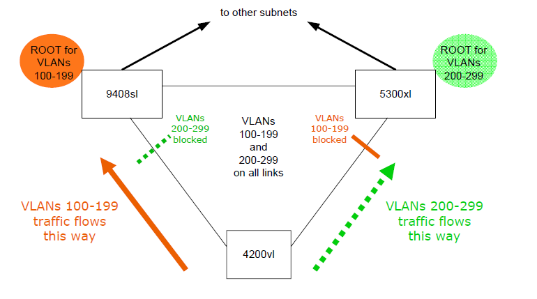 In this example, we see how the traffic of the 100-199 vlans will be blocked in one direction, while the vlans of the 200-299 will be allowed to pass through the blocked path. This improves network performance, since using STP or RSTP, one of these links would never be used.
Design of the MSTP: Regions
An MST region is one that shares the spanning-tree configuration.
The switches will be in the same region if you have the maximum:
- Name of region
- Revision number
- Mapping of VLAN-to-instance
So if we want to have several switches in the same region, what we will do is configure these same parameters in all the switches.
How to configure MSTP in HP switches?
Steps to configure the MSTP in an HP-2530 switch:
-
- Configure the VLANS
Configure the VLANS
- Define the MST
region
- Define the revision number in the MST region
- Define VLAN-to-instance mapping.
- Define the priority for each
- Define the cost of the path (path-cost)
- Define point-to-point links
- Enable MSTP
Example: Configure MSTP on switch HP 2530
We will take as an example the same scheme as in the aforementioned article.
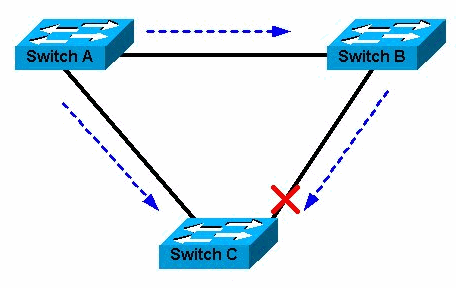
In this case all switches are HP2530 model.


Design conditions:
Switch A: Root for vlans 100-199
Switch B: Root for vlans 200-299
Switch C: You will have the ports blocked for each instance.
Switch A configuration:
mstp name mstp-example
mstp revision 10 mstp revision 10
mstp instance 1 vlan 100 to 199
mstp instance 1 priority 0
mstp instance 2 vlan 200 to 299
mstp instance 2 priority 4096
mstp instance 2 ethe 3/3 path-cost 30000
mstp admin-pt2pt-mac ethe 3/1 to 3/3
mstp start
Switch B configuration:
mstp name mstp-example
mstp revision 10 mstp revision 10
mstp instance 1 vlan 100 to 199
mstp instance 1 priority 4096
mstp instance 2 vlan 200 to 299
mstp instance 2 priority 0
mstp instance 2 ethe 3/3 path-cost 30000
mstp admin-pt2pt-mac ethe 3/1 to 3/3
mstp start
Swtich C configuration:
mstp name mstp-example
mstp revision 10
mstp instance 1 vlan 100 to 199
mstp instance 2 vlan 200 to 299
mstp start
With these commands and bearing in mind that the cables are connected correctly, we will have our equipment configured correctly.
If you have any questions, do not hesitate to comment or send me your questions.
See you in the nets!


Hi I am a student and I came across your article it is easy to understand but I have a few questions, please forgive me for my inexperience
1. If my understanding is correct all the switches need to have the same region-name but what is the purpose of the MSTP revision number, is it like VTP configuration revision number ?
2. Setting the Lowest Priority makes the Switch take precedence over the required VLAN instance but what is the use of these commands?
mstp instance 2 ethe 3/3 path-cost 30000
mstp admin-pt2pt-mac ethe 3/1 to 3/3
I understand p2pt means point to point
Thank you for sharing!
I’m new in the HP world. I come from Cisco and I find really difficult to find good documentation for HP switching in general.